This blog will explore the concepts of sensors and actuators in the context of Internet of Things (IoT), their types, applications, and how they work together in IoT systems.
📌 IoT Series (Part 3 of 5): This is the third article in our 5-part IoT series.

Table of contents
Open Table of contents
Sensors
What are sensors?
- Sensors are hardware devices that sense the physical world. It can measure one or more properties around and send the information to IoT device.
- Some common sensors include:
- Temperature sensors - sense air temperature, water temperature, humidity, air pressure.
- Buttons sensors - sense button press.
- Light sensors - sense light intensity/level.
- Camera sensors - sense image and video.
Use a sensor
In this blog, we will use CounterFit (a virtual IoT device simulator) to program and test sensors locally on your computer without needing physical hardware.
In this section, we will build a light sensor simulation application using Python.
- Hardware Concept: A physical light sensor uses a photodiode to convert light into an electrical signal.
- Data Type: Light sensors return analog values (integers indicating relative brightness, not mapped to a standard unit).
Step-by-step Guide: Connecting and Reading a Virtual Light Sensor
Step 1: Launch the CounterFit App Run the following command in your terminal:
counterfitThis starts the simulation web server at http://127.0.0.1:5000.
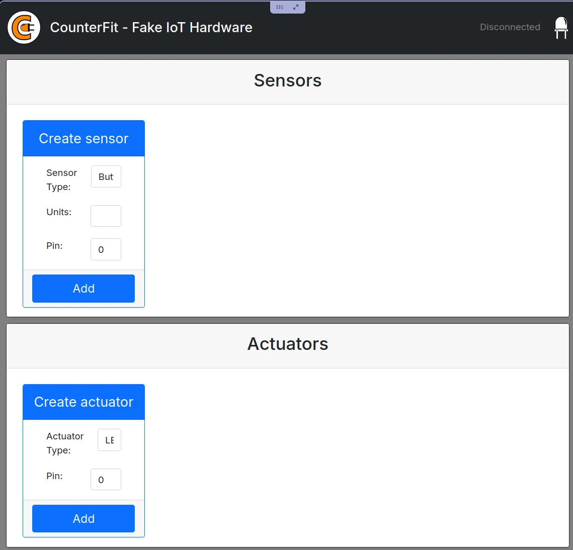
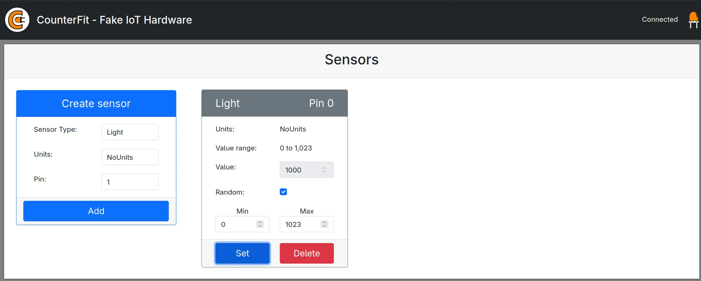
Step 2: Create the Virtual Light Sensor
- Open
http://127.0.0.1:5000in your web browser. - Under Sensors (left side):
- Set Sensor Type to
Light. - Set Pin to
0. - Click Add.
- Set Sensor Type to
Step 3: Write the Python Code (app.py)
Create app.py in your project folder with the following code:
import time
from counterfit_connection import CounterFitConnection
from counterfit_shims_grove.grove_light_sensor_v1_2 import GroveLightSensor

# 1. Connect to the local CounterFit simulation server
CounterFitConnection.init('127.0.0.1', 5000)

# 2. Initialize the Grove Light Sensor connected to Pin 0
light_sensor = GroveLightSensor(0)

# 3. Read and print light level every 1 second
while True:
    light = light_sensor.light
    print('Light level:', light)
    time.sleep(1)
Step 4: Execute the Application & Verify
- Open a new terminal window (keeping
counterfitrunning) and run:
python app.py-
CounterFit UI with Light Sensor Added:
-
Terminal Output Printing Light Level:
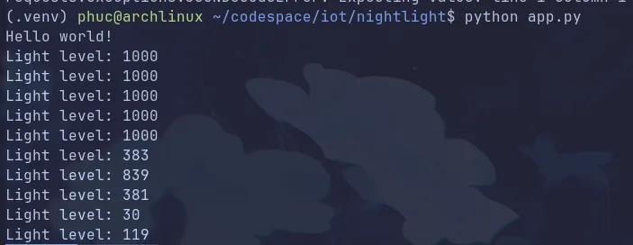
Verification: The light sensor will show active connection status in CounterFit UI, and your terminal will continuously print the current light readings!
Type of sensors
Analog sensors
- These sensors receive voltage from the IoT device and adjust it based on physical world properties (e.g. brightness or temperature).
Analog-to-Digital Conversion (ADC)
- Digital IoT devices only understand binary (
0s and1s). Therefore, analog voltage levels must be converted into digital numbers by an Analog-to-Digital Converter (ADC) (often built into the MCU or an expansion board/HAT). - Bit resolution of ADC usually 10 bits, converting analog values into digital values.
Example of Conversion Process:
- Analog Voltage: Sensor outputs
1.0V(on a3.3Vsystem). - Scaled Integer: ADC maps
1.0Vto an integer scale of0–1023→300. - Binary Conversion:
300is converted into binary0000000100101100for the CPU to process.
Digital sensors
Unlike analog sensors, digital sensors output digital signals (0s and 1s) directly to the IoT device, eliminating the need for an external ADC on the microcontroller or board.
They fall into two main categories:
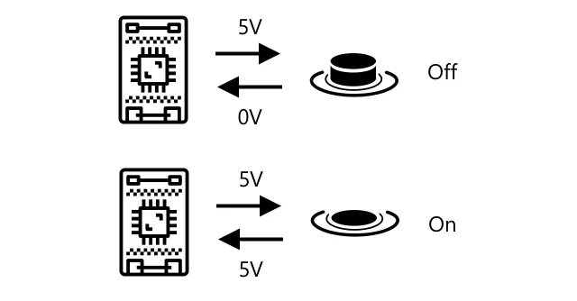
- Simple Binary Sensors (2-State)
- Example: Push buttons or switches.
- How it works:
- OFF State:
0Voutput → interpreted directly as0. - ON State:
3.3V(or5V) output → interpreted directly as1.
- OFF State:
- Voltage Threshold: GPIO pins read binary states directly (e.g., Raspberry Pi GPIO treats voltage
> 1.8Vas1and< 1.8Vas0).
- Advanced Digital Sensors (On-Board ADC)
- Example: Digital temperature sensors, digital cameras, or motion sensors.
- How it works: Contains an integrated on-board ADC that measures physical phenomena, converts it internally into binary bits (
0s and1s), and sends formatted data streams to the IoT device. - Complex Data: Allows sending rich, compressed data such as JPEG images or video streams frame-by-frame.
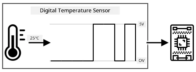
Key Advantage: Digital data transmission provides higher noise immunity, consistent precision, and support for encrypted payloads in secure IoT applications.
Actuators
What are actuators?
- Actuators are the opposite of sensors. They convert electrical signal from IoT device into interactions with physical world such as emitting light, sound, …
- Some common actuators are:
- LED - emit light
- Speaker - emit sound
- Stepper motor - convert signal into a defined amount of rotation, such as turning a dial 90 degrees.
Actuators can be seen as an end devices.
Use an actuator
In this section, you will add a virtual LED actuator to your IoT setup to create an automated Smart Nightlight: when the ambient light drops below 300, the LED turns ON; otherwise, it turns OFF.
- Hardware Concept: An LED (Light-Emitting Diode) is a digital actuator that emits light when an electrical voltage is applied.
- Actuator State: This is a digital actuator with 2 binary states: ON (
1/ high voltage) and OFF (0/ low voltage).
Step-by-step Guide: Connecting and Controlling a Virtual LED Actuator
Step 1: Create the Virtual LED Actuator in CounterFit
- Open
http://127.0.0.1:5000in your web browser. - Under Actuators (bottom left section):
- Set Actuator Type to
LED. - Set Pin to
5. - Click Add.
- Set Actuator Type to
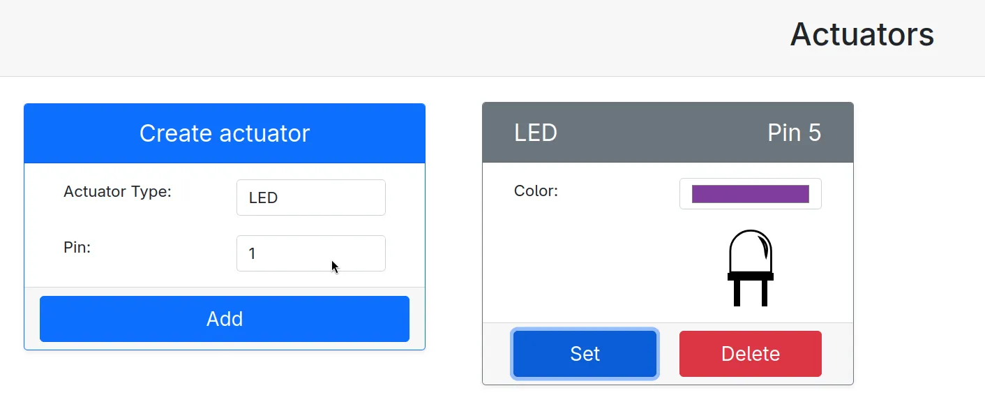
Step 2: Update Python Code (app.py)
Update your app.py script to control the LED based on light sensor readings:
import time
from counterfit_connection import CounterFitConnection
from counterfit_shims_grove.grove_light_sensor_v1_2 import GroveLightSensor
from counterfit_shims_grove.grove_led import GroveLed

# 1. Connect to local CounterFit simulation server
CounterFitConnection.init('127.0.0.1', 5000)
print('Connected to CounterFit server !!!')

# 2. Initialize LED Actuator on Pin 5 & Light Sensor on Pin 0
led = GroveLed(5)
light_sensor = GroveLightSensor(0)

# 3. Read light levels and trigger LED conditionally
while True:
    light = light_sensor.light
    print('Light level:', light)
    time.sleep(1)

    if light < 300:
        led.on()
    else:
        led.off()
Step 3: Run and Test the Nightlight
- In your terminal, run:
python app.py- In CounterFit UI under Sensors -> Light (Pin 0), adjust the Value slider:
- When light level < 300, the LED indicator turns ON (active color).
- When light level >= 300, the LED indicator turns OFF.
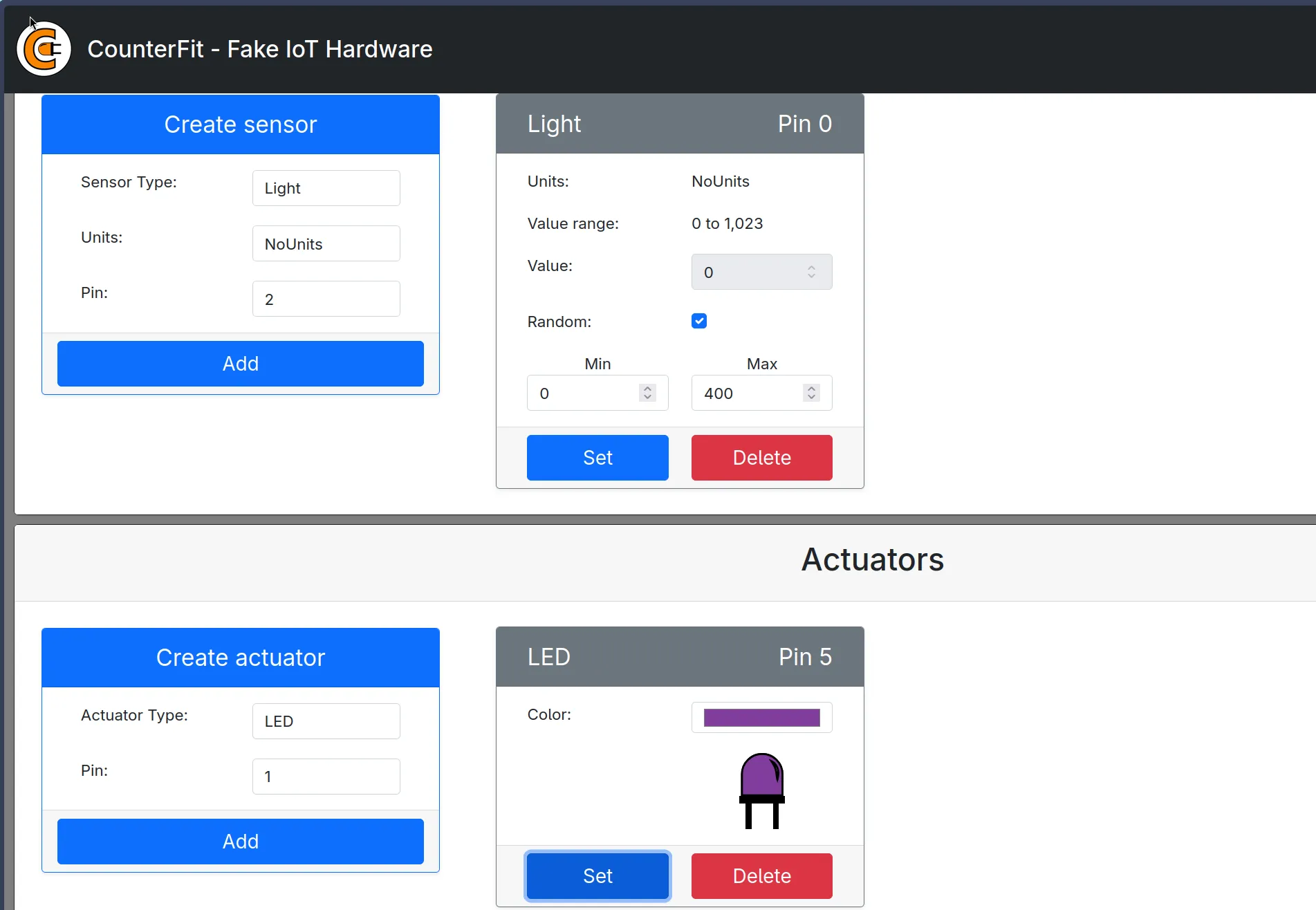
Verification: You have created a complete closed-loop IoT system! The sensor senses the environment (light level) and the MCU automatically commands the actuator (LED) to respond.
Type of actuators
Just like sensors, actuators are categorized into analog or digital.
Analog Actuators
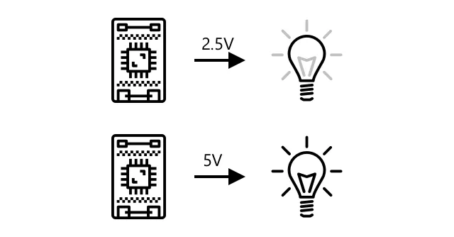
Analog actuators perform physical actions that vary continuously based on the exact voltage supplied to them.
- Real-world Example: A dimmable light bulb or variable-speed fan motor. The brightness or speed changes continuously according to the supplied voltage level (e.g.,
0V= OFF,1.65V= 50% brightness,3.3V= 100% brightness). - Digital-to-Analog Conversion (DAC): Because digital IoT devices only process binary (
0s and1s), sending an analog signal requires a Digital-to-Analog Converter (DAC) (on the MCU or expansion board) to convert binary bits into an analog voltage.
Digital Actuators
Unlike analog actuators, digital actuators operate directly on digital signals (0s and 1s) sent from the IoT device.
They operate in two primary ways:
-
Simple 2-State Digital Actuators:
- Example: An LED or relay switch.
- How it works:
- Signal
1(High Voltage): High voltage (e.g.,3.3Vor5V) is sent → turns the LED ON. - Signal
0(Low Voltage): Voltage drops to0V→ turns the LED OFF.
- Signal
-
Advanced Digital Actuators (On-Board DAC):
- Example: Digital servos, smart speakers, or display screens.
- How it works: Contains an integrated on-board DAC that accepts structured binary data commands from the MCU and converts them internally into precise analog actions or sound signals.
Digital actuators simplify hardware wiring because the microcontroller can drive binary states or send digital communication packets directly without requiring an external DAC board.
📖 Series Navigation
👈 Back to Part 2: Deeper Dive into Internet of Things (IoT)
👉 Continue to Part 4: Connect your device to the Internet