This blog is my diary recording my journey of learning about IoT, particularly the hardware devices used in IoT applications. I will introduce some basic hardware devices in IoT, including sensors and actuators.

Table of contents
Open Table of contents
- Sensor Devices
- Actuator Devices
Sensor Devices
Photoresistor Sensor (LDR Module) ☀️
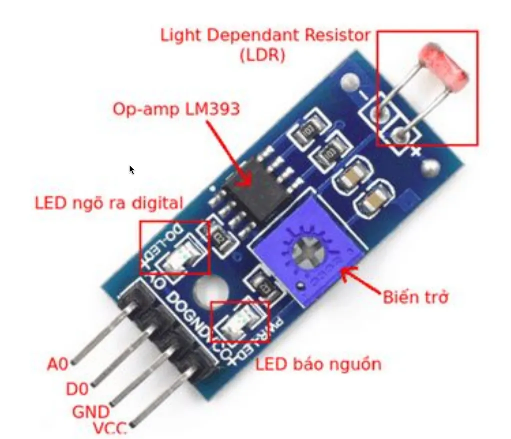 Figure 1: The standard 4-pin photoresistor (LDR) sensor module.
Main Components
- Light Dependent Resistor (LDR): Changes its resistance inversely with light intensity (high resistance in the dark, low resistance under bright light).
- Op-Amp (LM393): Compares the LDR’s voltage against a reference threshold to output a clean digital signal (
HIGHorLOW) on pin D0. - Potentiometer: Fine-tunes the sensitivity threshold for the digital output trigger.
- Power LED: Glows when the module receives proper power.
- D0 LED: Lights up when the digital output D0 is active.
Pinout
- VCC: Power supply pin ().
- GND: Ground ().
- D0: Digital output (
HIGH/LOWbased on the potentiometer threshold). - A0: Analog output (continuous voltage proportional to ambient brightness).
Simulation & Arduino Code ⚡
Here is a simple simulation circuit connecting an LDR with an Arduino Uno using a voltage divider configuration:
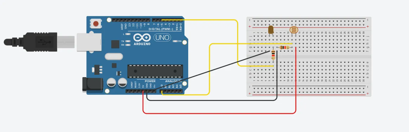 Figure 2: Breadboard simulation circuit connecting an LDR to Arduino Uno analog pin A0.
Circuit Connections
- 5V LDR: One leg connects to the 5V rail.
- LDR A0 & Resistor: The other leg connects to A0 and a pull-down resistor ().
- Resistor GND: The resistor connects to GND to complete the voltage divider.
Arduino Example Code
const int LDR_PIN = A0; // Connect to Analog pin A0

void setup() {
  Serial.begin(9600);
}

void loop() {
  int lightLevel = analogRead(LDR_PIN); // Reads value between 0 - 1023

  Serial.print("Ambient Light Level: ");
  Serial.println(lightLevel);

  delay(500); // Read every half second
}Higher ambient light reduces the LDR resistance, causing the voltage reading on A0 to increase towards . In pitch black, the value drops closer to .
Automatic Night Light: Integrating with an LED 💡
Now, let’s turn this into a real-world smart application: an automatic night light that turns an LED on when it gets dark and turns it off when the room is bright!
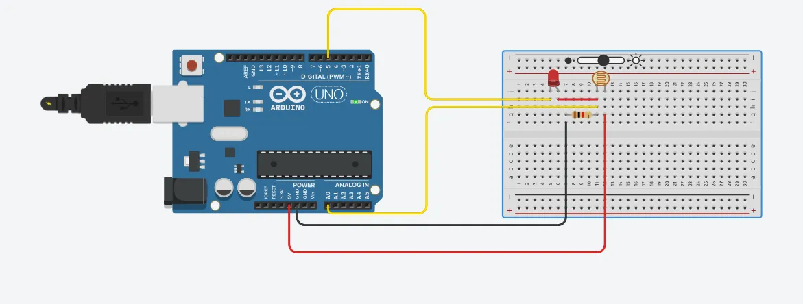 Figure 3: Arduino circuit controlling an LED based on LDR light readings.
Additional Circuit Connections
- Digital Pin 5 LED Anode (+): Connects to the positive leg of the LED to control power via code.
- LED Cathode (-) LDR / GND: Ground connection completes the circuit.
Arduino Example Code
const int LDR_PIN = A0;   // Photoresistor connected to Analog A0
const int LED_PIN = 5;    // LED connected to Digital Pin 5
const int THRESHOLD = 500; // Darkness threshold value

void setup() {
  pinMode(LED_PIN, OUTPUT);
  Serial.begin(9600);
}

void loop() {
  int lightLevel = analogRead(LDR_PIN);
  Serial.print("Light level: ");
  Serial.println(lightLevel);

  // If it's dark (reading below threshold), turn on the LED
  if (lightLevel < THRESHOLD) {
    digitalWrite(LED_PIN, HIGH);
  } else {
    digitalWrite(LED_PIN, LOW);
  }

  delay(200);
}
Ultrasonic Sensor (HC-SR04) 🦇
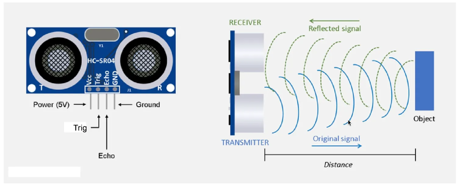 Figure 4: The HC-SR04 Ultrasonic distance sensor and its echo-ranging principle.
The HC-SR04 uses high-frequency sound waves (ultrasound at ) to measure distance without physical contact—just like bats navigate in the dark!
How It Works (Echo Principle)
- Trigger (Transmitter “T”): Sends out an ultrasonic sound burst (8 pulses at ).
- Reflect: The sound wave travels forward, hits an obstacle, and bounces back.
- Echo (Receiver “R”): Detects the reflected wave and outputs a pulse whose duration equals the round-trip travel time.
Pinout
- VCC: power supply.
- Trig (Trigger): Input pin to send the signal (set to
HIGHfor to trigger). - Echo: Output pin that stays
HIGHfor the duration of the sound’s travel time. - GND: Ground ().
Distance Formula
Since sound travels through air at approximately (or ), and the wave travels to the object and back:
Simulation & Arduino Code ⚡
Here is a simple simulation wiring the HC-SR04 with an Arduino Uno:
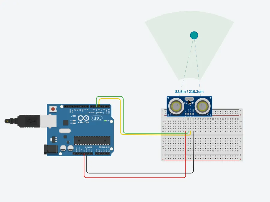 Figure 5: HC-SR04 ultrasonic sensor simulation connected to Arduino Uno pins 5 (Trig) and 4 (Echo).
Circuit Connections
- VCC 5V: Powers the sensor.
- GND GND: Ground reference.
- Trig Pin 5: Outputs pulses to fire ultrasonic bursts.
- Echo Pin 4: Reads the incoming pulse length from reflected sound.
Arduino Example Code
const int trigger_pin = 5;
const int echo_pin = 4;

void setup() {
    Serial.begin(9600);
    pinMode(trigger_pin, OUTPUT);
    pinMode(echo_pin, INPUT);
}

long getDistance() {
    digitalWrite(trigger_pin, LOW);
    delayMicroseconds(2);
    digitalWrite(trigger_pin, HIGH);
    delayMicroseconds(10);
    digitalWrite(trigger_pin, LOW);
    long duration = pulseIn(echo_pin, HIGH);
    long distance = duration * 0.034 / 2;
    return distance;
}

void loop() {
    int distance = getDistance(); // unit: cm
    Serial.print("Distance: ");
    Serial.print(distance);
    Serial.println(" cm");
    delay(200);
}Why on Trig?
HC-SR04 requires a HIGH pulse of at least to fire its 8-cycle ultrasonic burst (). The preceding LOW ensures a clean signal edge.
Push Button (Tactile Switch) 🔘
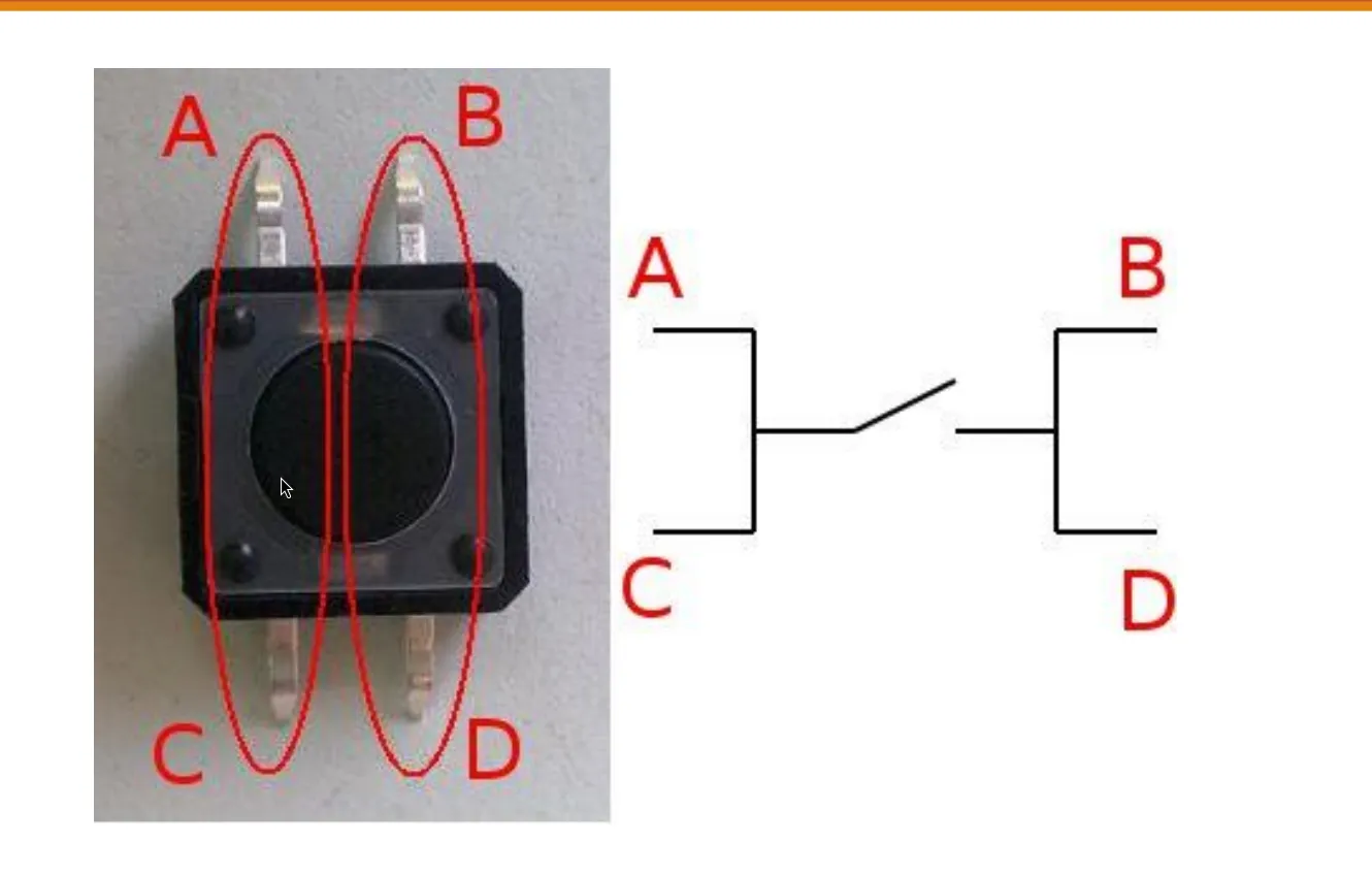 Figure 6: Tactile push button internal connection diagram.
A push button (or tactile switch) is an input sensor that connects two points in a circuit when pressed.
Pin Configuration
Although it has 4 pins, they are connected in pairs internally:
- Pin A is connected to Pin C
- Pin B is connected to Pin D
- When pressed, it connects (A, C) to (B, D) to close the circuit.
Simulation & Arduino Code ⚡
Here is a push button connected to an Arduino Uno using a pull-down resistor ():
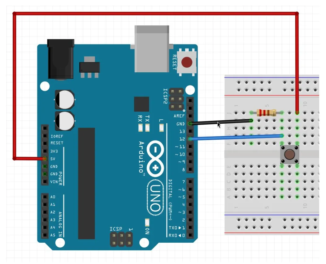 Figure 7: Push button circuit with a pull-down resistor connected to Arduino Pin 12.
Circuit Connections
- 5V Button Pin (B/D): Supplies 5V.
- Button Pin (A/C) Digital Pin 12: Reads button state (
HIGHorLOW). - Button Pin (A/C) Resistor () GND: Pulls pin to ground when released.
Why a pull-down resistor?
Without it, an unpressed button leaves the pin “floating” (reading random noise). The resistor holds the pin steadily at LOW () until pressed.
Arduino Example Code
const int BUTTON_PIN = 12;

void setup() {
  Serial.begin(9600);
  pinMode(BUTTON_PIN, INPUT);
}

void loop() {
  int buttonState = digitalRead(BUTTON_PIN);

  if (buttonState == HIGH) {
    Serial.println("Button Pressed!");
  } else {
    Serial.println("Button Released");
  }

  delay(200);
}
Potentiometer (Variable Resistor) 🎛️
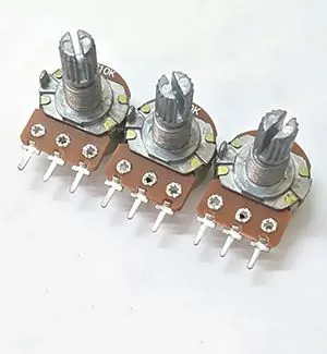 Figure 8: Rotary potentiometers (variable resistors).
A potentiometer (biến trở) is a 3-terminal variable resistor. Turning its knob adjusts electrical resistance, producing a variable output voltage that functions as an adjustable voltage divider.
3-Terminal Pinout
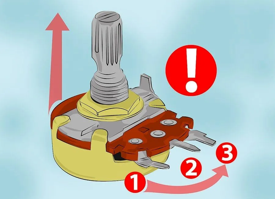 Figure 9: Potentiometer 3-pin configuration and internal wiper diagram.
| Pin | Connected To | Description |
|---|---|---|
| 1 (Terminal 1) | Arduino GND | Ground reference (or 5V) |
| 2 (Wiper / Output) | Arduino Analog Pin (A0) | Variable voltage output () |
| 3 (Terminal 2) | Arduino 5V | Power supply (or GND) |
Pins 1 and 3 are interchangeable. Swapping them simply reverses which direction of knob rotation increases or decreases the reading. The center pin (Pin 2) is always the wiper signal output.
Simulation & Arduino Code ⚡
Here is a potentiometer connected to an Arduino Uno on analog pin A0:
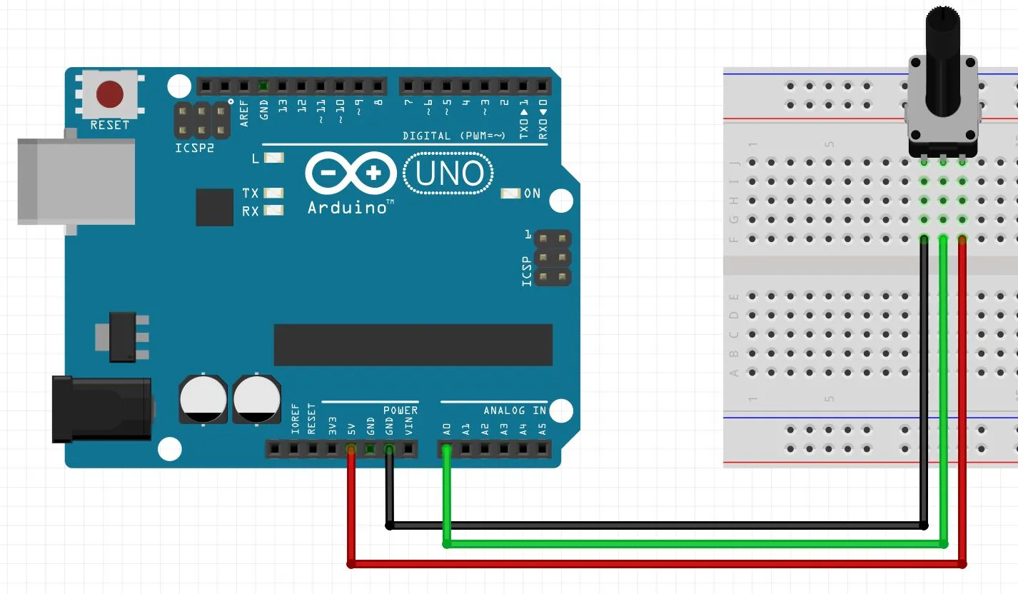 Figure 10: Potentiometer wired to Arduino Uno analog pin A0.
Circuit Connections
- Pin 1 GND
- Pin 2 (Wiper) Analog Pin A0
- Pin 3 5V
1. Basic Analog Reading
The Arduino reads the voltage on pin A0 as a 10-bit integer from 0 () to 1023 ():
const int POT_PIN = A0;

void setup() {
  Serial.begin(9600);
  pinMode(POT_PIN, INPUT);
}

void loop() {
  int value = analogRead(POT_PIN); // Reads 0 to 1023
  Serial.println(value);
  delay(100);
}
2. Controlling LED Brightness (Dimming)
Translate the 10-bit analog reading () to an 8-bit PWM value () using map(), and drive an LED on Pin ~6 with analogWrite():
const int POT_PIN = A0;
const int LED_PIN = 6; // PWM pin

void setup() {
  pinMode(POT_PIN, INPUT);
  pinMode(LED_PIN, OUTPUT);
  Serial.begin(9600);
}

void loop() {
  int value = analogRead(POT_PIN);               // Range: 0 - 1023
  int led_value = map(value, 0, 1023, 0, 255);   // Convert to PWM: 0 - 255
  analogWrite(LED_PIN, led_value);               // Adjust LED brightness
  delay(100);
}
Actuator Devices
Buzzer (Active & Passive) 🔊
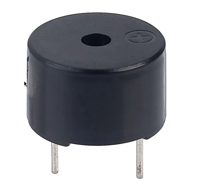 Figure 11: A standard buzzer module.
A buzzer is a small component that makes sound—like beeps, clicks, or alarms.
Active vs. Passive Buzzer
There are two main types of buzzers:
| Feature | Active Buzzer 🟢 | Passive Buzzer 🔵 |
|---|---|---|
| How it works | Has a built-in sound generator | Needs an external sound wave |
| How to control | Just turn power on/off (HIGH / LOW) | Send frequencies using tone() |
| Sound | One fixed “beep” sound | Can play different musical notes |
| Best used for | Simple warning beeps & alarms | Songs, melodies, and sound effects |
Pins (Polarity)
- Longer leg (+): Marked with a
+on the plastic cap Connect to an Arduino digital pin (or ). - Shorter leg (-): Connect to
GND.
Simulation & Arduino Code 🎵
Here is a simple simulation wiring a buzzer to an Arduino Uno to play a melody:
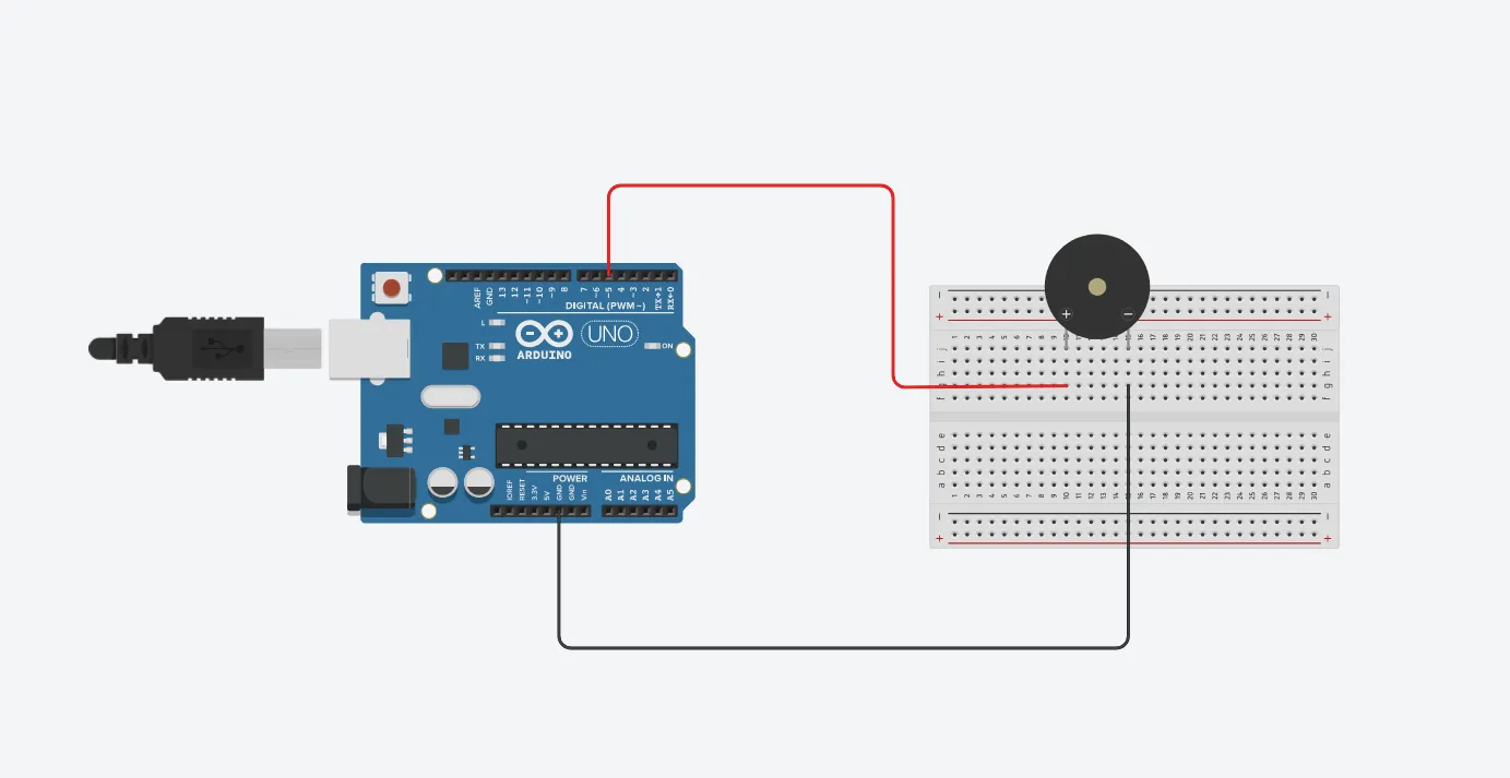 Figure 12: Buzzer simulation connected to Arduino Uno Pin 5 and GND.
Circuit Connections
- Positive Pin (+) Digital Pin 5: Sends frequency pulses to produce sound notes.
- Negative Pin (-) GND: Ground reference.
Arduino Example Code
int buzzer_pin = 5;

void setup() {
  pinMode(buzzer_pin, OUTPUT);
}

void loop() {
  int notes_len = 25;
  int frequency[] = {262, 262, 294, 262, 349, 330, 262, 262, 294, 262,
  392, 349, 262, 262, 523, 440, 349, 330, 294, 466, 466, 440, 349, 392, 349};
  float duration[] = {0.5, 0.5, 1, 1, 1, 2, 0.5, 0.5, 1, 1, 1, 2, 0.5,
  0.5, 1, 1, 1, 1, 3, 0.5, 0.5, 1, 1, 1, 2};

  for (int i = 0; i < notes_len; i++) {
    tone(buzzer_pin, frequency[i], duration[i] * 1000);
    delay(500);
  }
  noTone(buzzer_pin);
}tone(pin, frequency, duration)sends a sound frequency (in Hz) to the buzzer for a set duration.noTone(pin)shuts off the sound when the melody finishes.
Relay Module 🔌
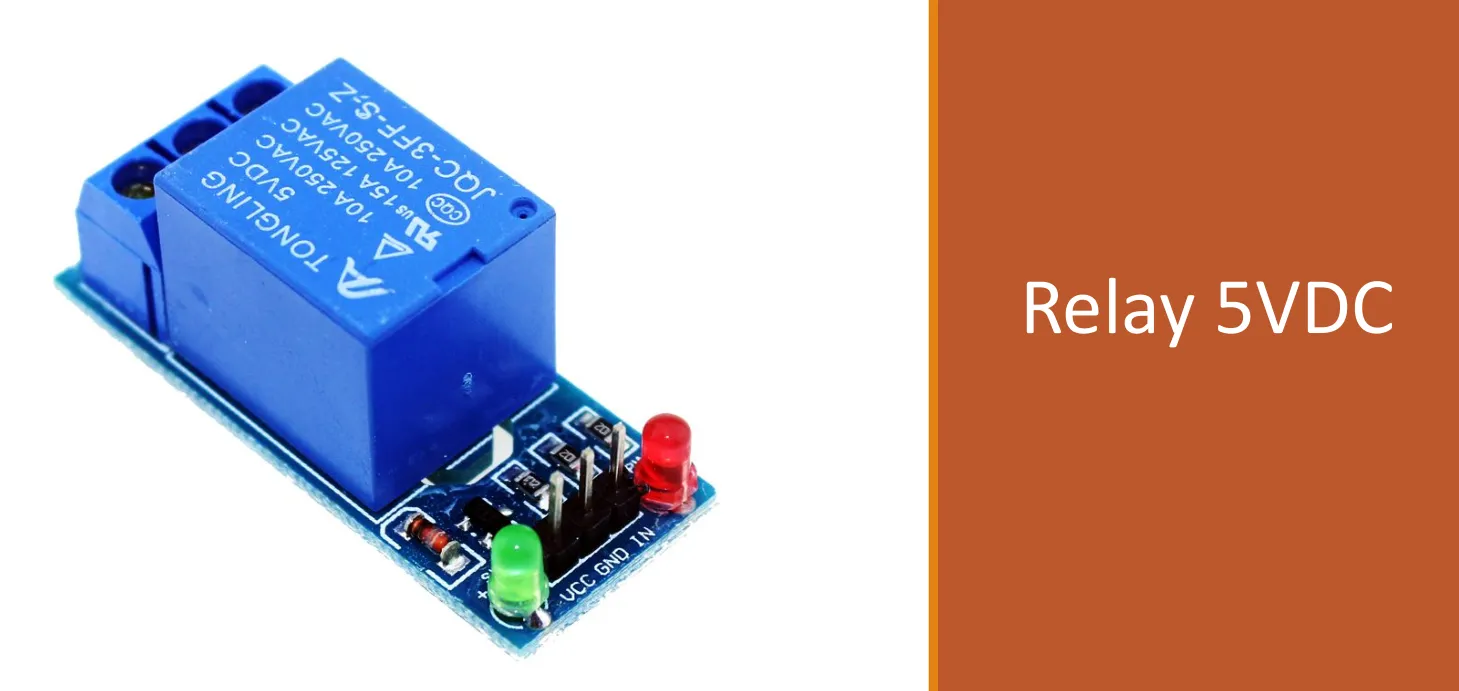 Figure 13: A standard 5VDC single-channel relay module.
A relay is an electrically operated switch. It allows a low-power microcontroller (like an Arduino running on ) to safely turn on and off high-power electrical devices (like light bulbs, fans, or motors).
What does “5VDC” mean?
- Coil power:
VCCrequires a constant DC to power the internal electromagnet. - Triggering: While
VCCis always , theINpin depends on the module: Active-HIGH triggers on (HIGH), while Active-LOW (common in Arduino kits) triggers on (LOW).
How It Works (Working Mechanism)
Inside the relay is an electromagnet and a physical mechanical switch:
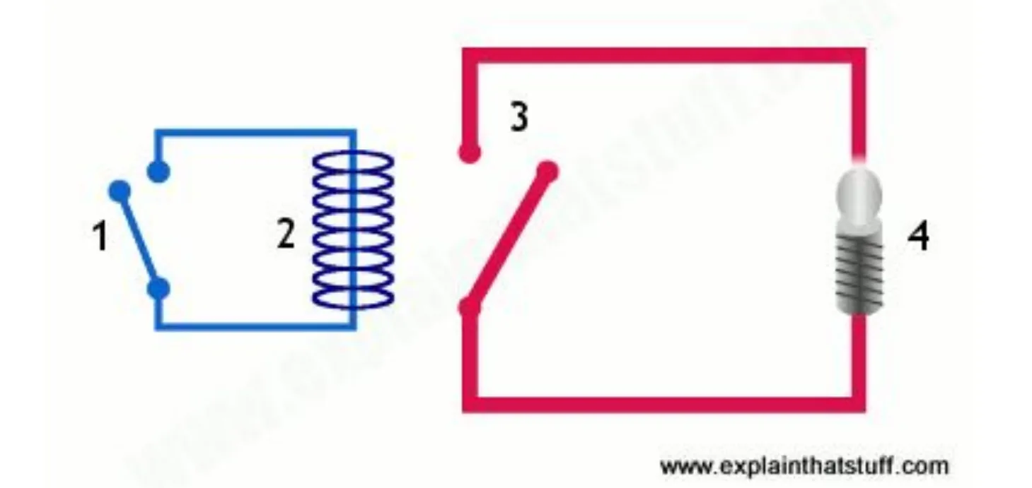 Figure 14: Internal working mechanism of an electromagnetic relay.
- Control Signal (1): The microcontroller sends a small signal to the relay.
- Electromagnet Coil (2): Current flows through the coil, creating a magnetic field.
- Movable Switch (3): The magnet pulls the contact arm closed (this makes the characteristic “click” sound!).
- High-Power Load (4): The high-voltage circuit completes, safely powering the light bulb or appliance.
When the signal turns off, the magnetic pull stops, and an internal spring pulls the switch back open to disconnect power.
Terminals & Pinout Breakdown
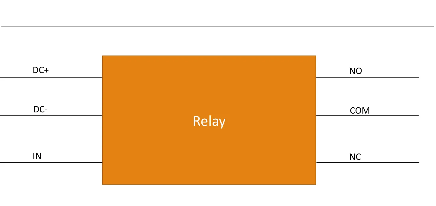 Figure 15: Relay module terminal connections (Control side vs. High-power load side).
A relay module has two separate sides:
1. Control Side (Low Voltage - Arduino):
- DC+ (VCC): Connects to Arduino 5V to power the electromagnet coil.
- DC- (GND): Connects to Arduino GND.
- IN (Signal): Receives the digital trigger command from an Arduino pin.
2. Load Side (High Voltage - Appliances):
- COM (Common): The shared terminal connected to one side of the external power supply.
- NO (Normally Open): Disconnected by default (circuit is open / device is OFF). When triggered, COM connects to NO device turns ON (most common use case).
- NC (Normally Closed): Connected by default (device is ON). When triggered, COM disconnects from NC device turns OFF.
Circuit Integration: Controlling an AC Light Bulb 💡
Here is how an Arduino Uno safely controls an AC light bulb using the relay module:
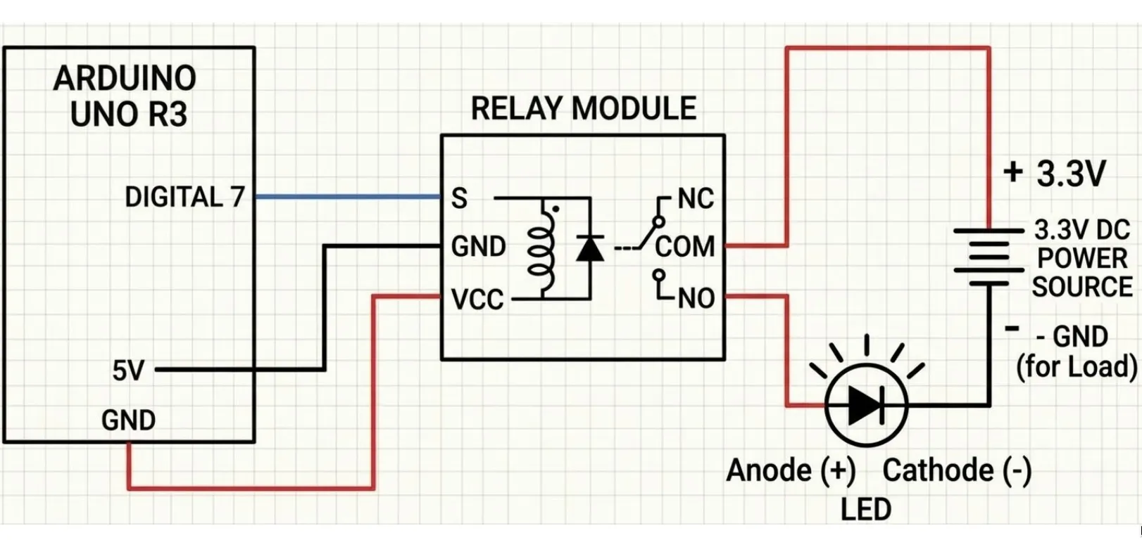 Figure 16: Wiring diagram of an Arduino controlling an AC light bulb via relay.
Circuit Connections
- Arduino Relay (Control Side):
- 5V VCC: Powers the internal coil.
- GND GND: Common ground reference.
- Digital Pin 7 S (Signal): Sends switching commands.
- Relay Light Bulb (AC Load Side):
- AC Power Source COM.
- NO Light Bulb.
- Light Bulb Return AC Power Neutral.
Arduino Example Code
const int RELAY_PIN = 7;

void setup() {
  pinMode(RELAY_PIN, OUTPUT);
}

void loop() {
  // Turn ON the light bulb (for Active-HIGH modules)
  digitalWrite(RELAY_PIN, HIGH);
  delay(3000); // Wait 3 seconds

  // Turn OFF the light bulb
  digitalWrite(RELAY_PIN, LOW);
  delay(3000); // Wait 3 seconds
}Complete electrical isolation: the control side and high-voltage AC side never touch, protecting your Arduino from surges.
SPDT Relay (Single Pole Double Throw) 🔀
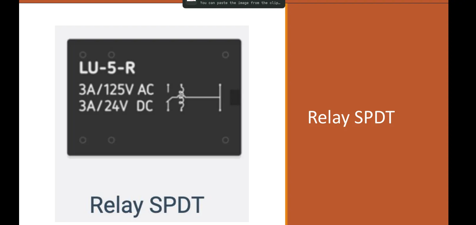 Figure 17: A standalone SPDT relay component (LU-5-R).
The most common mechanical relay used in electronics and simulation platforms (such as Wokwi) is the SPDT (Single Pole Double Throw) relay:
- Single Pole (SP): One common input switch contact (
COM). - Double Throw (DT): Two possible connection paths (
NOandNC). The single switch “throws” between either NO or NC.
SPDT Pinout Configuration
Standalone SPDT relays feature 6 pins directly on the casing:
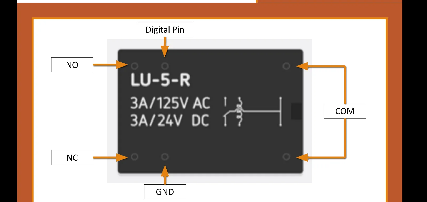 Figure 18: 6-pin SPDT relay layout and connection mapping.
- Coil Terminals (Control):
- Digital Pin (top-middle): Connects to the Arduino digital output pin to control switching.
- GND (bottom-middle): Connects to circuit ground.
- Switch Contacts (Load):
- COM (Common - right pins): Both pins on the right side are connected internally as the common terminal.
- NO (Normally Open - top-left): Normally disconnected from
COM. Connects when the coil is energized. - NC (Normally Closed - bottom-left): Normally connected to
COM. Disconnects when the coil is energized.
Digital Pin as direct power source:
Unlike the 3-wire module above (which has separate VCC power and IN signal pins), this standalone SPDT relay has no VCC pin. The Arduino Digital Pin itself directly powers the coil with when set to HIGH.
Practical Simulation: Switching a DC Light Bulb with a 9V Battery 💡
Here is a practical simulation wiring an SPDT relay to control a DC light bulb powered by an external 9V battery:
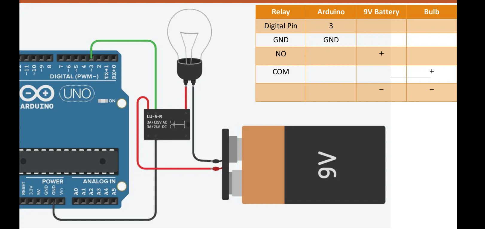 Figure 19: Arduino controlling a 9V battery-powered bulb through an SPDT relay.
Connection Table
| Relay Pin | Arduino Uno | 9V Battery | Bulb |
|---|---|---|---|
| Digital Pin | Pin 3 | — | — |
| GND | GND | — | — |
| NO | — | Positive (+) | — |
| COM | — | — | Positive (+) |
| — | — | Negative (-) | Negative (-) |
How It Works
- Battery connects directly to Bulb .
- Battery connects to NO, and Bulb connects to COM.
- Setting Arduino Pin 3 to
HIGHbridges COM NO, completing the 9V circuit to light the bulb.
Arduino Example Code
const int RELAY_PIN = 3;

void setup() {
  pinMode(RELAY_PIN, OUTPUT);
}

void loop() {
  // Turn ON the bulb for 2 seconds
  digitalWrite(RELAY_PIN, HIGH);
  delay(2000);

  // Turn OFF the bulb for 2 seconds
  digitalWrite(RELAY_PIN, LOW);
  delay(2000);
}
LCD 16x2 Display 📟
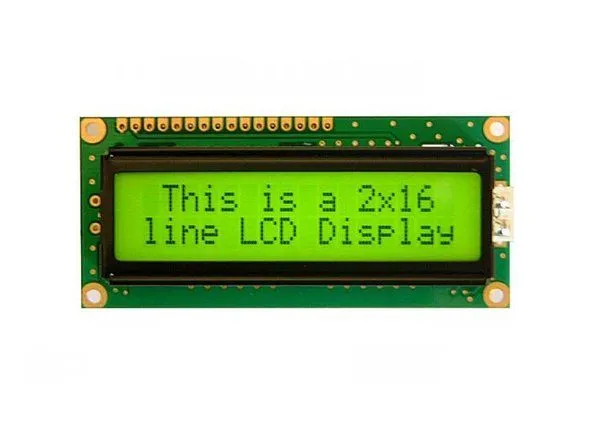 Figure 20: A standard 16x2 Liquid Crystal Display (LCD).
An LCD (Liquid Crystal Display) 16x2 displays visual text, numbers, and symbols across 2 rows of 16 characters.
16-Pin Pinout Breakdown
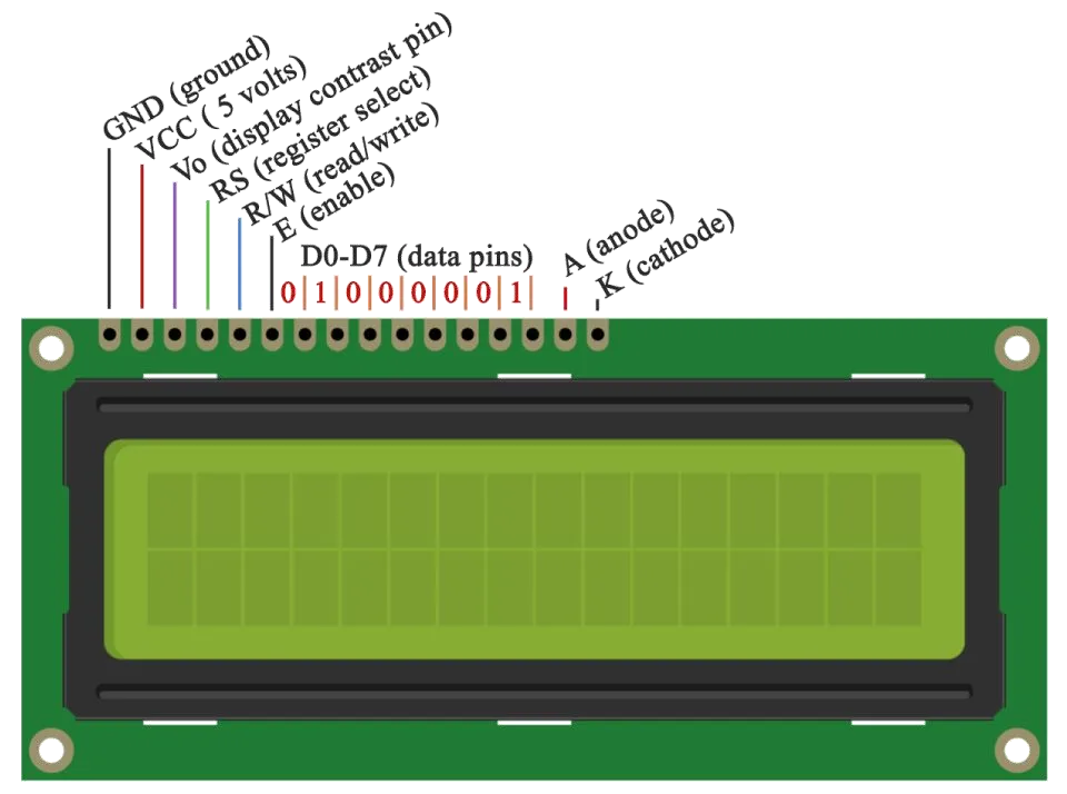 Figure 21: LCD 16x2 pinout and functional signal lines.
The 16 pins are divided into four main roles:
- Power & Contrast:
- VSS (GND) & VDD (5V): Power supply.
- V0 (VEE): Contrast adjustment pin connected to the wiper (center pin) of a potentiometer.
- Control Pins:
- RS (Register Select):
LOWfor command instructions (clear screen, move cursor);HIGHfor display data. - RW (Read/Write):
LOWfor Write (tied toGND);HIGHfor Read. - E (Enable): Executes data when receiving a falling edge pulse (
HIGHLOW).
- RS (Register Select):
- Data Pins (D0 - D7): Parallel data bus. In 4-bit mode, only D4 - D7 are used to save Arduino pins.
- Backlight LED:
- A (Anode): Backlight (via resistor).
- K (Cathode): Backlight ground (
GND).
4-Bit Parallel Mode: Wiring & Simulation ⚡
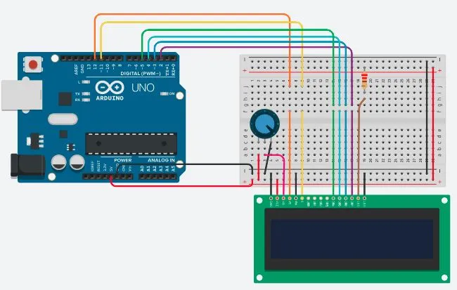 Figure 22: Arduino Uno controlling an LCD 16x2 in 4-bit mode with contrast potentiometer.
Connection Table
| LCD Pin | Connected To | Purpose |
|---|---|---|
| VSS, RW, K | Arduino GND | Ground references |
| VDD | Arduino 5V | Logic power |
| V0 | Potentiometer Center Pin | Contrast tuning |
| RS | Arduino Pin 12 | Register select |
| E | Arduino Pin 11 | Enable clock |
| D4, D5, D6, D7 | Arduino Pins 5, 4, 3, 2 | 4-bit data bus |
| A | Arduino 5V (via ) | Backlight power |
Arduino Example Code (LiquidCrystal.h)
#include <LiquidCrystal.h>

// Initialize library with interface pins: RS, E, D4, D5, D6, D7
LiquidCrystal lcd(12, 11, 5, 4, 3, 2);

void setup() {
  lcd.begin(16, 2);              // Set up columns and rows
  lcd.print("Hello, World!");    // Print message on row 0
}

void loop() {
  lcd.setCursor(0, 1);           // Move cursor to column 0, row 1
  lcd.print(millis() / 1000);    // Print seconds elapsed
}
Upgrade: LCD with I2C Module (Save Wiring) 🚀
Standard 4-bit parallel wiring takes up at least 6 digital GPIO pins. An I2C backpack module soldered onto the back reduces all connections to just 4 wires!
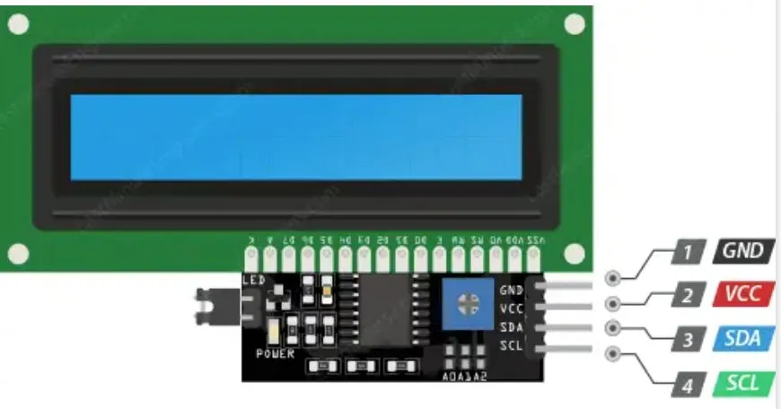 Figure 23: LCD 16x2 equipped with an I2C adapter backpack.
I2C Pin Connections
- GND GND
- VCC 5V
- SDA Pin A4 (Serial Data on Arduino Uno)
- SCL Pin A5 (Serial Clock on Arduino Uno)
- Most LCD I2C backpacks use the address
0x27(or0x3F). - Contrast can be adjusted using the small blue potentiometer directly on the I2C backpack.
Arduino I2C Code (LiquidCrystal_I2C.h)
#include <Wire.h>
#include <LiquidCrystal_I2C.h>

// Set the LCD address (0x27 or 0x3F) for a 16 chars and 2 line display
LiquidCrystal_I2C lcd(0x27, 16, 2);

void setup() {
  lcd.init();
  lcd.backlight();               // Turn on LCD backlight
  lcd.setCursor(0, 0);
  lcd.print("Hello World!");
}

void loop() {
  // Blinking backlight example
  lcd.backlight();
  delay(1000);
  lcd.noBacklight();
  delay(1000);
}
Servo Motor (Micro Servo SG90) 🦾
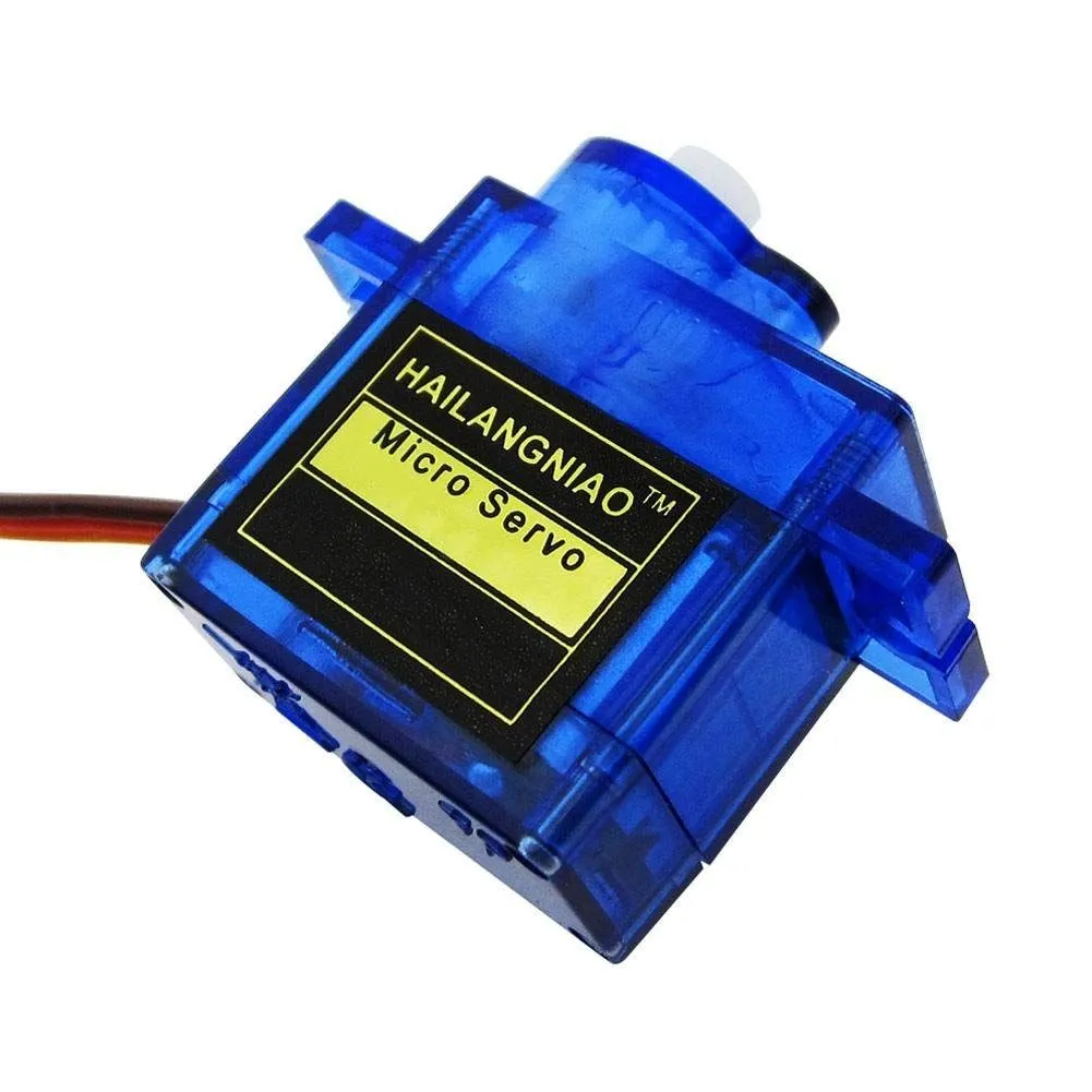 Figure 24: Micro Servo SG90 motor.
A servo motor is an actuator designed for precise angular position control. Unlike regular DC motors that spin continuously, a standard micro servo rotates precisely between and .
3-Wire Pinout
| Wire Color | Connected To | Function |
|---|---|---|
| Red | Arduino 5V | Power supply |
| Brown / Black | Arduino GND | Ground reference |
| Orange / Yellow | Arduino PWM Pin (~9) | Control signal pulse |
Simulation & Arduino Code ⚡
Here is a simple simulation wiring a micro servo to an Arduino Uno:
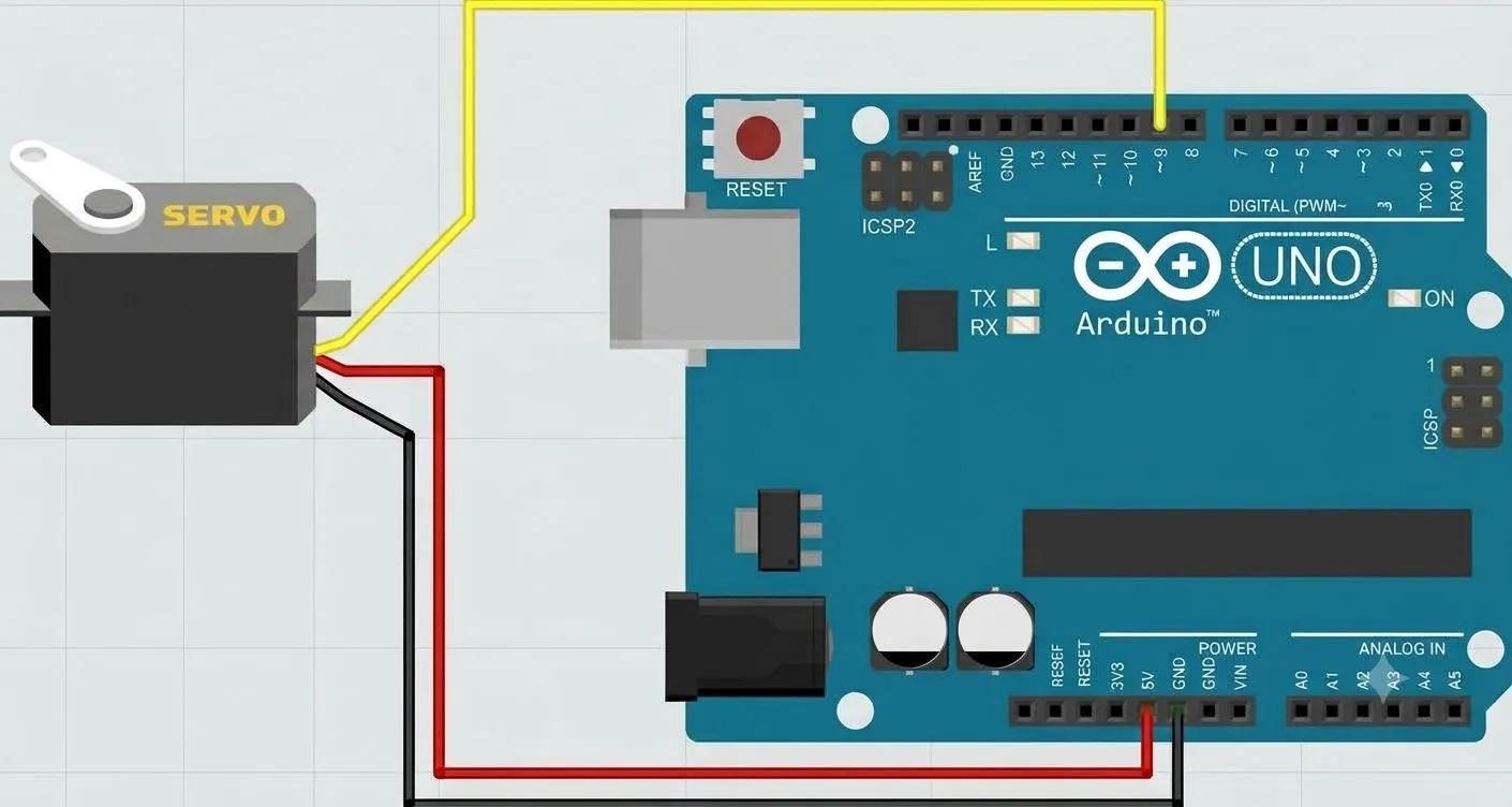 Figure 25: Micro Servo connected to Arduino Uno Pin ~9 (PWM), 5V, and GND.
Basic Angle Control (Servo.h)
#include <Servo.h>

Servo myservo; // Create servo object

void setup() {
  myservo.attach(9); // Attach servo to digital pin 9
}

void loop() {
  myservo.write(0);    // Rotate to 0 degrees
  delay(1000);
  myservo.write(90);   // Rotate to 90 degrees (center)
  delay(1000);
  myservo.write(180);  // Rotate to 180 degrees
  delay(1000);
}
Practical Control: Steering with a Potentiometer
Using Arduino’s map() function, you can translate the potentiometer’s analog input ( on pin A0) directly into an angle ():
#include <Servo.h>

Servo myservo;
const int POT_PIN = A0;

void setup() {
  myservo.attach(9);
}

void loop() {
  int val = analogRead(POT_PIN);          // Read potentiometer (0 - 1023)
  int angle = map(val, 0, 1023, 0, 180);  // Map to servo angle (0 - 180)
  myservo.write(angle);                   // Command servo to rotate
  delay(15);                              // Short wait for movement
}